Why is the five-axis CNC machine tool five-axis linkage, not six-axis linkage?
Release time:2024-06-04
Why is the five-axis CNC machine tool five-axis linkage, not six-axis linkage?
The fundamental reason that the machine tool can achieve arbitrary Angle machining is that the tool or probe can approach the workpiece in any direction. The five-axis linkage is the least linkage axis, which can realize the processing at any Angle. Typically, only five axes are adaptive. This is because the less the linkage shaft, the simpler and more compact the machine structure, and it is easy to ensure the dynamic and static stiffness of the machine tool. Dynamic and static stiffness are crucial for machine tools that require very high accuracy.
One concept may stick in our brains. In 3D space, an object has six degrees of freedom (DF). As shown below.
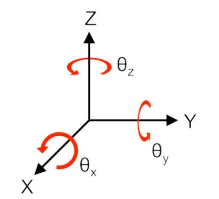
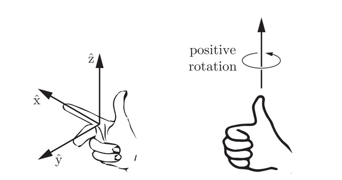
This is a right-handed coordinate system. The six degrees of freedom (DF) are the three linear degrees of freedom along the X, Y, and Z axes; And three degrees of freedom around the X, Y, and Z axes. The positive direction of rotation satisfies the right-hand spiral rule. As shown below.
Because of the influence of this concept, we may think that the machine tool needs 6 degrees of freedom or 6 axes if it needs to achieve machining in any direction. In fact, the object has 6 degrees of freedom, which does not mean that the machine needs to be composed of 6 axes to achieve arbitrary Angle machining. This is the crux of the matter.
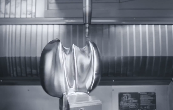
When a traditional three-axis machine tool processes a workpiece consisting of complex surfaces or holes in multiple directions. We need to use special jigs and make a lot of changes in the process to ensure that the tool can touch the workpiece from any direction. When the five-axis CNC machine tool is used, the high-speed and high-precision machining of the complex shape workpiece can be realized with one clamping.
That is to say, the tool or probe can approach the workpiece in any direction, which is the key for the machine to be able to achieve any direction of processing.
The machine implements machining by controlling the position and attitude of the tool or probe. Therefore, the key point or premise is how to describe the position and attitude of the tool or probe.
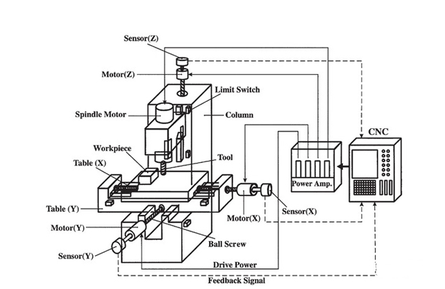
Three-axis CNC machine tool
In the process of three-axis CNC machine tool, the position of the tool or probe is changed, but its attitude is fixed. For example, the general vertical three-axis machine tool processing tool direction is Z-axis forward. The position and attitude of the tool or probe can be determined according to the linear axis coordinates of X, Y, and Z.
Five-axis CNC machine tool
Under normal circumstances, the 5-axis machine tool adds two rotating axes to the 3-axis machine tool. In general, the A, B, and C axes represent the axis of rotation around the X, Y, and Z linear axes. The 5-axis machine consists of any two axes, A, B and C.
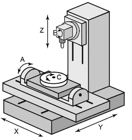
Please note that the figure above only shows the relationship between the rotating axis and the linear axis, and is not the actual configuration of the 5-axis machine. In fact, the rotation axis of the 5-axis machine tool is composed of two axes, A, B and C. For example, A and B, or A and C, or B and C.
Due to the presence of these two rotating axes, the position and attitude of the tool or probe will change during five-axis machining. Obviously, after the reference point on the spindle is determined, the position of the tool or probe can be determined by the straight axis X, Y, B. Of course, in actual operation, it is also necessary to consider the distance from the rotating center to the tip of the knife and the influence of the rotation Angle.
But what about the posture of the tool or probe?
In order to describe the attitude of tool or probe during machining or testing, the concept of tool axis vector is derived. The knife axis vector is a three-dimensional unit vector (i,j,k). Each element corresponds to the projected value of the unit vector in the direction of the knife axis, which is projected on the straight axes X, Y, and Z.
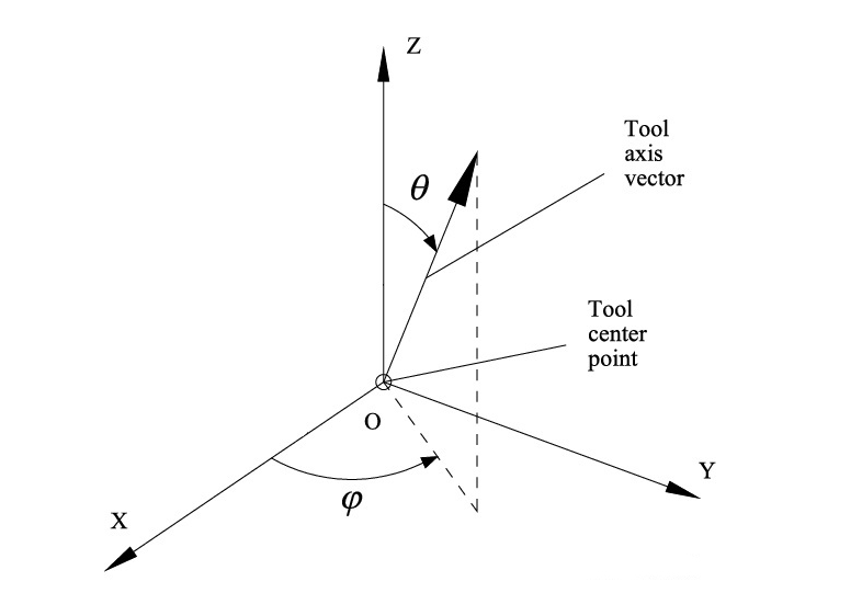
Since the knife axis vector is a unit vector with a modulus length of 1, all possible positions of the knife axis vector vertices in space form a sphere of radius 1.
Any tool axis vector direction can be obtained by rotating a vector in space around two non-collinear axes in space.
This sounds abstract, but there is a good example in our daily lives. Longitude and latitude, the o and 0 in the figure above. We can determine any location on the Earth's surface by longitude and latitude. Longitude and latitude consist of only two coordinates, which can be described by the Angle between two vertical axes of rotation.
In the figure below, when determining the position of a point on the sphere, each point corresponds to a knife axis vector, which can be described in two coordinate systems.
1. Use the spherical coordinate system on the left, also known as the explicit expression of spherical coordinates. That's longitude and latitude, and it's made up of two coordinates, so it corresponds to two degrees of freedom, because longitude and latitude are independent of each other.
2. Use the XYZ system on the right, also known as implicit expression. Contains three coordinates, but still corresponds to two degrees of freedom. Because these three coordinates contain an implicit constraint.
x^2+y^2+z^2=1
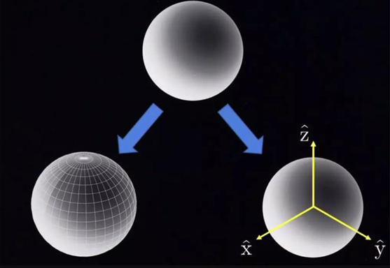
Thus, the Angle of rotation of the two rotational axes can describe a definite position on the sphere. The projected values of X, Y, Z forward of the determined sphere position are used to describe the tool axis vector (i,j,k) of the tool or probe attitude.
In this way, the rotation Angle of the two axes and the knife axis vector establish a one-to-one correspondence. In the actual five-axis machining, the numerical system will obtain the respective rotation angles of the two rotation axes according to the numerical program of the tool axis vector, and the kinematic relationship. The system will then control these two rotational axes and the three linear axes, combined with the coordinates of the linear axes. This allows the tool or probe to move to a predetermined position and posture.
A popular but not very rigorous method, as long as two more rotating axes are added to the three-axis machine tool, the tool can be controlled to approach the workpiece in any direction, and the processing of any complex surface can be realized.
If the machine tool adds two rotating axes on the basis of the 3-axis machine tool, and applies the numerical control system, servo system and RTCP(rotating tool center point), you can achieve 5-axis linkage machining, then it can be called a 5-axis linkage CNC machine tool.
Why don't 5-axis machines use more linkage axes?
On the one hand, five linkage axes are the minimum number of linkage axes to achieve arbitrary Angle machining. We explained why in the previous paragraph. On the other hand, usually only five axes are applied. Because the fewer the linkage shaft, the simpler the machine structure, the more impact, the easier it is to ensure the dynamic and static stiffness of the machine. Dynamic stiffness and static stiffness are very important for CNC machine tools that require high precision. But this will not affect the birth of higher axis motor. This type of machine tool is mainly produced to meet obstacle avoidance or special optimization objectives. Such as minimum motor power. In order to meet these special requirements, there are too many cases in which the linkage shaft is increased at the expense of dynamic and static stiffness.
Why does a five-axis machine need only five linkage axes to achieve arbitrary Angle machining? The key is that only two rotational degrees of freedom are needed to express the knife axis vector in any direction.